
I get to do all sorts of practical stuff at work, some of which has nothing to do with physiology or imaging. One such thing is producing custom-made cables and plugs. Since I’ve had the pleasure of doing a fair few of these recently, I thought I’d put up a short how-to blog post on wiring up a DIN connector.
DIN stands for Deutsches Institut fur Normung, which translates to the German Institute for Standardisation. A DIN connector is, in short, a standardized connector, which come in a similar size. You may have seen them as they are often used for analog audio. The male DIN plug is typically 13.2 mm in diameter, and it often has a notch at the bottom to make sure the plug goes in the right way. Male plugs have a set of round pins, 1.45mm in diameter, that are equally spaced within the plug. The different types of DIN plugs have different numbers and configurations of pins. Below is an overview of some typical pin configurations.

There are, of course, variations over these themes, as well as specialized plugs with more than 10 pins. Pins on male connectors are numbered. The numbering* goes from right to left, viewed from the outside of the connector with the pins upward and facing the viewer. The female counterparts are the inverse of the male plugs, and their numbering is from left to right. Usually, only corresponding male-female pairs work together, but you may be able to fit a 3-pin plug with a 5-pin 180 degree plug.
*EDIT: to clarify, the numbering of the pins are not in order, as pointed out in the comments (thank you!). For the plugs, a 5-pin plug would be numbered (from right to left for the male, and from left to right for the female): 1–4–2–5–3.
So how to attach a DIN plug to a cable?
- Take the cable and snip off a few centimetres of plastic and remove padding. Snip off the insulation (about 1 cm) of the individual internal cables (cores). Slide the DIN metal sheet over the wire.
- Make sure that each core fits neatly into holes of DIN plug. This might mean cutting some of the wires. Move the unisolated wires (the ground) to one side.
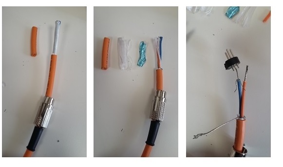
- Solder the core wires together and test that they still fit the holes in the plug.
- (Now comes the fiddly part). Add solder tin (a small amount is best) to the DIN plug holes, heat with the solder and push the tinned cores into holes. Remove solder iron and let the tin solidify (a few seconds only). Test that the solder holds by pulling firmly on the plug and cores. Attach the metal clamp around the cores (see second of figures below).
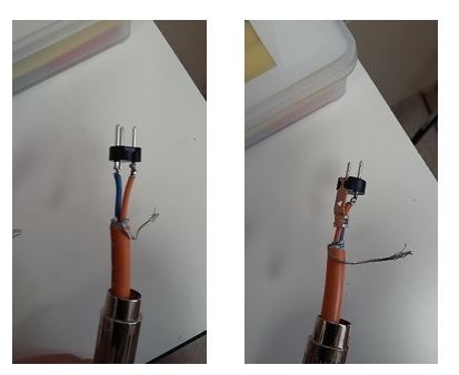
- Wrap the ground wires around the base of the metal clamp. Make sure the ground does NOT touch the cores. Test that there is no connection between wires and between wires and ground using a multimeter. Slide the metal sheet over the structure and plastic, and screw on the release catch where this overlays hole on metal clamp.

Done.

Mari,
Thank you for making an interesting blog site! I particularly enjoyed your page on MRI magnet mistakes.
Anyway, I thought I should point out a misunderstanding on your DIN plug wiring page. You wrote: “The numbering goes from right to left, viewed from the outside of the connector with the pins upward and facing the viewer”. However, although this is entirely logical it is not correct! You can find information on the correct wiring at Wikipedia here: https://en.wikipedia.org/wiki/DIN_connector
and here: https://www.electronics2000.co.uk/pin-out/dincon.php
Kind regards,
Mike H
LikeLike
Hi Mike. You are, of course, absolutely correct. I didn’t even think about the numbers, so thanks for pointing out that it was misleading. Have edited it above! Feel free to point out if you see anything else – I always try (and clearly sometimes fail) to make things as clear and accurate as possible.
Glad you enjoyed the MRI magnet mistakes post! I find it hugely interesting, so it is always nice that others like the topic too.
LikeLike
I need advise on how to connect santan Jack to 4 pins midi piano pedal?
LikeLike